Homemade HomeKit (with an ESP8266 microcontroller)
homelab linux iot HomeKit-ifying every last corner of my apartment - for better or worse - has become a “hobby” of mine as of lately. After stumbling upon Andrew Ngai’s awesome YouTube video on designing and implementing his own HomeKit accessory, I too felt inspired to hack around a bit.
Setup
Arduino IDE
We’ll be using the Arduino IDE to write our firmware to our development module.
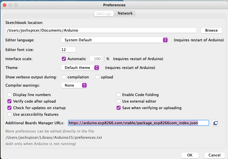
First, add the following “Additional Boards Manager URL” in the IDE’s Preferences.
http://Arduino.esp8266.com/stable/package_esp8266com_index.json
The source code and docs for this module live here.
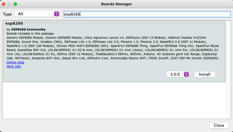
Then, in Tools > Board: X > Board Manager, search and install the ESP8266 board manager.
I bought these development boards from Amazon. In the product description they provided additional instructions on setup. Your specific board may have different settings, mine instructed me to –
- Set ESP8266 board type to `NodeMCU 1.0 (ESP-12E Module)
- Set Flash Size to
4M - Set CPU Freqency to
80 Mhz - Set bod speed to
921600
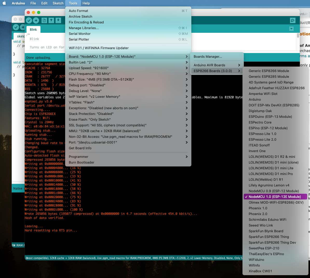
I then simply attached my device via microUSB, selected my device via the “port”, and ran the Arduino pre-installed “Blink” example program. After uploading the program, the embedded LED on the device began to blink. We’re in business!
The program output looked like this:
Executable segment sizes:
ICACHE : 32768           - flash instruction cache
IROM   : 231756          - code in flash         (default or ICACHE_FLASH_ATTR)
IRAM   : 26777   / 32768 - code in IRAM          (IRAM_ATTR, ISRs...)
DATA   : 1496  )         - initialized variables (global, static) in RAM/HEAP
RODATA : 876   ) / 81920 - constants             (global, static) in RAM/HEAP
BSS    : 25608 )         - zeroed variables      (global, static) in RAM/HEAP
Sketch uses 260905 bytes (24%) of program storage space. Maximum is 1044464 bytes.
Global variables use 27980 bytes (34%) of dynamic memory, leaving 53940 bytes for local variables. Maximum is 81920 bytes.
esptool.py v3.0
Serial port /dev/cu.usbserial-0001
Connecting....
Chip is ESP8266EX
Features: WiFi
Crystal is 26MHz
MAC: e8:db:84:e3:1a:c1
Uploading stub...
Running stub...
Stub running...
Changing baud rate to 460800
Changed.
Configuring flash size...
Auto-detected Flash size: 4MB
Compressed 265056 bytes to 195077...
Writing at 0x00000000... (8 %)
Writing at 0x00004000... (16 %)
Writing at 0x00008000... (25 %)
Writing at 0x0000c000... (33 %)
Writing at 0x00010000... (41 %)
Writing at 0x00014000... (50 %)
Writing at 0x00018000... (58 %)
Writing at 0x0001c000... (66 %)
Writing at 0x00020000... (75 %)
Writing at 0x00024000... (83 %)
Writing at 0x00028000... (91 %)
Writing at 0x0002c000... (100 %)
Wrote 265056 bytes (195077 compressed) at 0x00000000 in 4.7 seconds (effective 454.0 kbit/s)...
Hash of data verified.

Leaving...
Hard resetting via RTS pin...
GPIO Pins
Here I found the pin-out of my specific board –
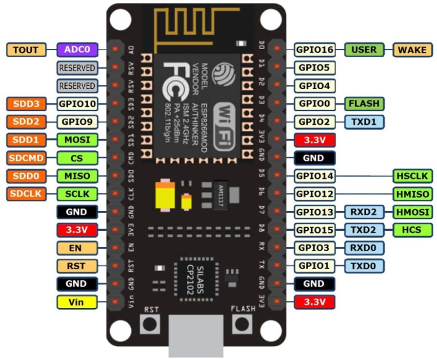
As a PoC I decided to break out my tiny breadboard, some LEDs, and write a couple lines of code to flash them. The result – some pretty colors!
#define LED_RED 1
#define LED_YELLOW 3
#define LED_GREEN 15

#define NUM_LEDS 3

int values[NUM_LEDS]  = { LED_RED, LED_YELLOW, LED_GREEN };

// the setup function runs once when you press reset or power the board
void setup() {

  pinMode(LED_RED, OUTPUT);
  pinMode(LED_YELLOW, OUTPUT);
  pinMode(LED_GREEN, OUTPUT);
}

// the loop function runs over and over again forever
void loop() {
  // Wait a sec
  delay(1000);

  // Cascade the LEDs on
  for (int i = 0; i < NUM_LEDS; i++) {
    digitalWrite(values[i], HIGH);
    delay(500);
  }

  // Wait a sec
  delay(1000);

  // Cascade the LEDs off
  for (int i = 0; i < NUM_LEDS; i++) {
    digitalWrite(values[NUM_LEDS - i - 1], LOW);
    delay(500);
  }
}
HomeKit
Great, we now have the board and our IDE talking to each other. Next, I took a peek at Mixiaoxiao’s Arduino-Homekit-ESP8266 library on GitHub, which implements the HomeKit Specification.
Simply download a ZIP of the repo above, navigate to Sketch > Include Library > Add .ZIP Library, and select the downloaded ZIP. You can then select this library in the Sketch’s settings.
Below is a modified example Sketch that maps each of our three LEDs to a homekit virtual switch.
/*
 * switch.ino
 *
 *  Created on: 2020-05-15
 *      Author: Mixiaoxiao (Wang Bin)
 *  Modified on: 2021-05-17
 *      Modifier: Josh Spicer <hello@joshspicer.com>
 */

#include <Arduino.h>
#include <arduino_homekit_server.h>
#include "wifi_info.h"

#define LOG_D(fmt, ...)   printf_P(PSTR(fmt "\n") , ##__VA_ARGS__);

void setup() {
  Serial.begin(115200);
  wifi_connect(); // in wifi_info.h
  //homekit_storage_reset(); // to remove the previous HomeKit pairing storage when you first run this new HomeKit example
  my_homekit_setup();
}

void loop() {
  my_homekit_loop();
  delay(10);
}

//==============================
// HomeKit setup and loop
//==============================

// access your HomeKit characteristics defined in my_accessory.c
extern "C" homekit_server_config_t config;

extern "C" homekit_characteristic_t red_led;
extern "C" homekit_characteristic_t green_led;
extern "C" homekit_characteristic_t yellow_led;

static uint32_t next_heap_millis = 0;

#define PIN_SWITCH 2
#define LED_RED 15
#define LED_YELLOW 3
#define LED_GREEN 1

//Called when the switch value is changed by iOS Home APP
void green_led_setter(const homekit_value_t value) {
  bool on = value.bool_value;
  green_led.value.bool_value = on;  //sync the value
  LOG_D("Green Switch: %s", on ? "ON" : "OFF");
  digitalWrite(LED_GREEN, on ? HIGH : LOW);
}

//Called when the switch value is changed by iOS Home APP
void red_led_setter(const homekit_value_t value) {
  bool on = value.bool_value;
  red_led.value.bool_value = on;  //sync the value
  LOG_D("Red Switch: %s", on ? "ON" : "OFF");
  digitalWrite(LED_RED, on ? HIGH : LOW);
}

//Called when the switch value is changed by iOS Home APP
void yellow_led_setter(const homekit_value_t value) {
  bool on = value.bool_value;
  red_led.value.bool_value = on;  //sync the value
  LOG_D("Yellow Switch: %s", on ? "ON" : "OFF");
  digitalWrite(LED_YELLOW, on ? HIGH : LOW);
}

void my_homekit_setup() {
  pinMode(PIN_SWITCH, OUTPUT);
  digitalWrite(PIN_SWITCH, HIGH);

  pinMode(LED_GREEN, OUTPUT);
  pinMode(LED_YELLOW, OUTPUT);
  pinMode(LED_RED, OUTPUT);

  red_led.setter = red_led_setter;
  yellow_led.setter = yellow_led_setter;
  green_led.setter = green_led_setter;
  arduino_homekit_setup(&config);
}

void my_homekit_loop() {
  arduino_homekit_loop();
  const uint32_t t = millis();
  if (t > next_heap_millis) {
    // show heap info every 5 seconds
    next_heap_millis = t + 5 * 1000;
    LOG_D("Free heap: %d, HomeKit clients: %d",
        ESP.getFreeHeap(), arduino_homekit_connected_clients_count());

  }
}
/*
 * my_accessory.c
 * Defines the accessory in C  using the Macro in characteristics.h
 *
 *  Created on: 2020-05-15
 *      Author: Mixiaoxiao (Wang Bin)
 *   Modified on: 2021-05-17
 *      Modifier: Josh Spicer <hello@joshspicer.com>
 */

#include <homekit/homekit.h>
#include <homekit/characteristics.h>

void my_accessory_identify(homekit_value_t _value) {
  printf("accessory identify\n");
}

homekit_characteristic_t green_led = HOMEKIT_CHARACTERISTIC_(ON, false);
homekit_characteristic_t yellow_led = HOMEKIT_CHARACTERISTIC_(ON, false);
homekit_characteristic_t red_led = HOMEKIT_CHARACTERISTIC_(ON, false);


homekit_accessory_t *accessories[] = {
    HOMEKIT_ACCESSORY(.id=1, .category=homekit_accessory_category_switch, .services=(homekit_service_t*[]) {
        HOMEKIT_SERVICE(ACCESSORY_INFORMATION, .characteristics=(homekit_characteristic_t*[]) {
            HOMEKIT_CHARACTERISTIC(NAME, "Breadboard"),
            HOMEKIT_CHARACTERISTIC(MANUFACTURER, "Arduino HomeKit"),
            HOMEKIT_CHARACTERISTIC(SERIAL_NUMBER, "0123456"),
            HOMEKIT_CHARACTERISTIC(MODEL, "ESP8266/ESP32"),
            HOMEKIT_CHARACTERISTIC(FIRMWARE_REVISION, "1.0"),
            HOMEKIT_CHARACTERISTIC(IDENTIFY, my_accessory_identify),
            NULL
        }),
        HOMEKIT_SERVICE(SWITCH, .primary=true, .characteristics=(homekit_characteristic_t*[]) {
            &green_led,
            HOMEKIT_CHARACTERISTIC(NAME, "Green LED"),
            NULL
        }),
        HOMEKIT_SERVICE(SWITCH, .characteristics=(homekit_characteristic_t*[]) {
            &yellow_led,
            HOMEKIT_CHARACTERISTIC(NAME, "Yellow LED"),
            NULL
        }),
        HOMEKIT_SERVICE(SWITCH, .characteristics=(homekit_characteristic_t*[]) {
            &red_led,
            HOMEKIT_CHARACTERISTIC(NAME, "Red LED"),
            NULL
        }),
        NULL
    }),
    NULL
};

homekit_server_config_t config = {
    .accessories = accessories,
    .password = "111-11-111"
};
/*
 * wifi_info.h
 *
 *  Created on: 2020-05-15
 *      Author: Mixiaoxiao (Wang Bin)
 *   Modified on: 2021-05-17
 *      Modifier: Josh Spicer <hello@joshspicer.com>
 */

#ifndef WIFI_INFO_H_
#define WIFI_INFO_H_

#if defined(ESP8266)
#include <ESP8266WiFi.h>
#elif defined(ESP32)
#include <WiFi.h>
#endif

const char *ssid = "your_ssid";
const char *password = "your_pw";

void wifi_connect() {
  WiFi.persistent(false);
  WiFi.mode(WIFI_STA);
  WiFi.setAutoReconnect(true);
  WiFi.begin(ssid, password);
  Serial.println("WiFi connecting...");
  while (!WiFi.isConnected()) {
    delay(100);
    Serial.print(".");
  }
  Serial.print("\n");
  Serial.printf("WiFi connected, IP: %s\n", WiFi.localIP().toString().c_str());
}

#endif /* WIFI_INFO_H_ */
Give it a little bit to initialize after flashing, and then go manually add the accessory in your Home app.
After a minute more or so, your switches will be ready for use!
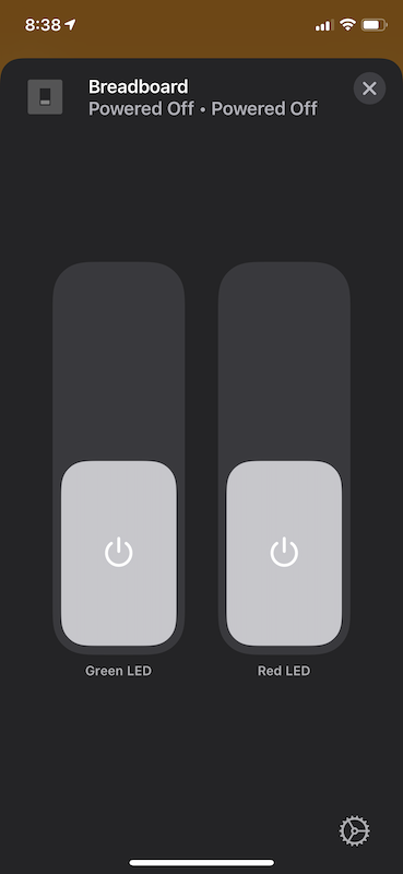
And in action…
Have a comment? Join the discussion
This post helpful? Buy me a coffee!